Since the compass is a main data source for the ENC, you need to set and calibrate it very precisely.
Did you know that 5 degrees compass error, on distance of 1000m, leads to almost 90m error?
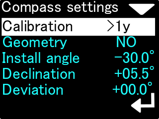
Calibration
The information on the right is the time that has elapsed since the last calibration (in minutes, hours, days or ‘> 1y’ if the time is greater than 1 year).
This option is used for basic magnetometer calibration. You should use this function, when the compass direction shown on this device is improper. This is usually needed when the magnetic properties of the environment have changed.
In every location, magnetic background, declination and other magnetometer-influencing factors are different. Thus, the compass should be calibrated every time, when the location is changed, especially when there are big distances travelled (travelling to another continent, or to a distant country).
Current settings
After selecting MENU → SETUP → Compass → Calibration, we will be moved to the next menu, containing information and commands for calibrating the compass. The screen is shown on the pictures below:
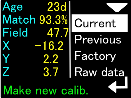
The compass calibration current values contain the following information:
Age
Calibration age (time elapsed since the last calibration).
Match
Estimated quality of performed calibration. A value below 80% may indicate a device fault or external interference during calibration. The ideal calibration should be 92-95% of this parameter.
Field
The length of the magnetic field vector at the calibration site. The value is expressed in microtesla (uT). The correct value of the magnetic field strength can be found using, for example, this website:
https://www.ngdc.noaa.gov/geomag/calculators/magcalc.shtml#igrfwmm
If the value given by the ENC in this field differs by more than 10% from the expected value of the field strength (given by the online calculator), we have reason to assume that the calibration has been disturbed or there are local magnetic anomalies at the calibration site.
X, Y, Z
Exact values of the magnetometer calibration coefficients. You can use them for comparison purposes (for subsequent calibrations)
The values in the factory calibration screen have the same meaning but refer to the settings that the device received at the time of manufacture (can be used for comparison).
When Current is highlighted, pressing the new button starts the compass calibration process.
Previous settings
When the Previous field is highlighted, we can see the calibration settings that the console had previously. The device stores one previous compass calibration in its memory. Pressing the lower button when the Previous field is highlighted will cause the current compass calibration to take the values saved previously (e.g. from a month or a week ago)
Factory settings
When the Factory field is highlighted, we see the factory calibration properties.
These are the parameters that the device had when the factory tests were carried out. Pressing the console’s lower button while Factory is highlighted will restore the compass to factory calibration.
Factory calibration is correct for the place where the device was manufactured. In another part of the world, the readings of such a calibrated compass may differ significantly from the correct values.
If the compass still does not work after factory calibration has been restored – e.g. shows only one value or it only changes by a few degrees – it means a defect in the device that can only be diagnosed by factory service.
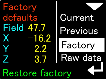
The screen for restoring the calibration settings to the factory values
Calibrating the compass after a reset
If a factory reset of the compass has made it unblocked, try a regular calibration to get the best readings:
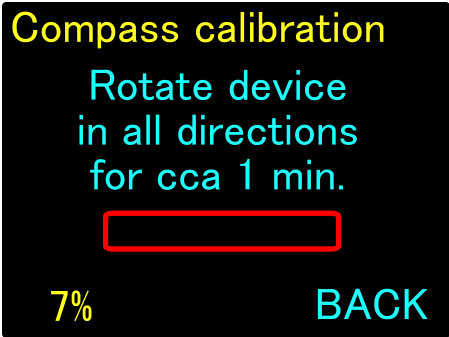
While calibrating the compass, you should slowly- without rapid movements- turn it in all possible directions (“tilting the eighths while turning around”). The screen displayed during this operation has not changed from the previous version. The only addition is the digital “calibration progress percentage” indicator that appears at the bottom left of the screen.
However, the internal procedure for obtaining compass calibration data completely changes.
Previously, calibration was simply measured by its duration. It was up to the diligence of the user whether after the calibration was completed its result would be good or not.
In the current software version, an advanced algorithm analyzes the operations performed by the user while calibrating the device. The progress bar and digital indicator on the screen reflect the actual operation progress.
If the user does not rotate the device as it should, or rotates it only in one axis all the time, the progress bar and digital indicator will remain unchanged and may even roll back after 5 minutes of inactivity.
Calibration is successful when the progress bar turns green and the digital indicator is at least 70%. At this point, the text in the lower right corner of the screen will change to APPLY, and the user by pressing the lower navigation button will save the new calibration values to the device memory.
The top navigation button during the entire calibration process is used to abort the operation without saving the data.
The maximum value shown in the digital progress indicator field is 120%. This means that 20% more data has been collected than is necessary to accurately calculate the compass calibration.
Preview of current sensor values
The last function available in the compass calibration menu is the function of displaying the current values measured by the sensors of the ENC console. We activate this function by highlighting Raw data on the compass calibration screen.
By pressing the lower button of the console, we change the view of the previewed data, as shown in the figures below:
Magnetometer raw data
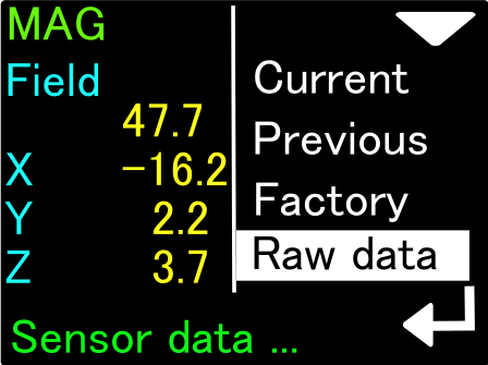
The data of the magnetometer (Mag) can be used, for example, when looking for a good place to mount the ENC console. If the total value of the magnetic field (Field) oscillates, for example, around the number 47.7uT (as in the picture above) and we bring our ENC console closer to the scooter, we can observe a change in the Field value. If this change is large (above 10%), then the place where we placed the ENC console is not suitable for mounting it, as it is under the influence of some disturbing magnetic interference.
Similarly, we can test equipment elements by bringing them closer to the ENC console. Changing the Field value will show us what objects generate or change the magnetic field and should be placed away from our ENC.
Accelerometer raw data
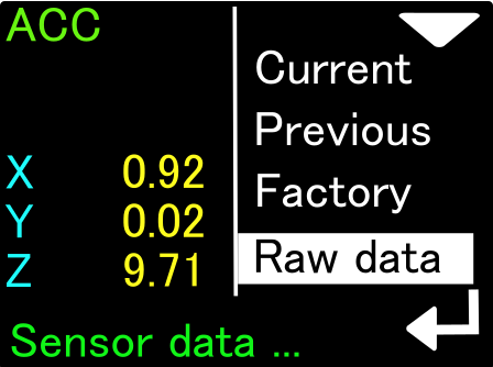
Accelerometer (ACC) data is needed to determine console tilt. The values on this screen are accelerations expressed in m / s2. If we place the console perfectly vertical, the value on one of the axes (X, Y or Z) should be close to 9.81 (this is the average acceleration due to gravity), and the other values should be close to 0. If the acceleration due to gravity cannot be observed, or when the vertically positioned device does not show zero on at least 2 axes, it may indicate its damage (e.g. due to a very strong impact).
The compass may not be correct in this case.
Gyroscope raw data
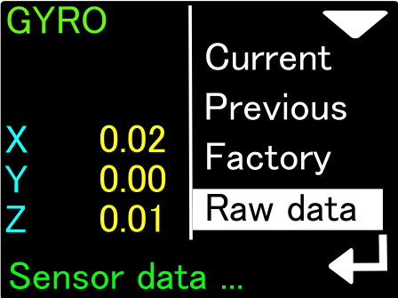
The gyro data (GYRO) is used to determine the compass direction when there is a sharp change in speed or direction. When at rest, the measurements of this sensor should be very close to 0 (acceptable values 0 … 0.02). If it is not, the gyroscope may be damaged, which can negatively affect compass calculations.
EULER angles
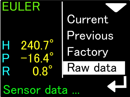
The last screen (EULER) is the result of the direct operation of the ENC console’s computational algorithms. The given angles are: H – Heading = compass heading without declination and deviation corrections), P – Pitch = ascent or descent grade, for ascent the values are positive, for descent – negative, R – Roll = side to side, a positive value means tilt to the right, negative – to the left.
If the Euler angle indications do not work as described, the device must be reset to factory settings and then carefully calibrated from the beginning. When that doesn’t help, the ENC console should be returned for service.
Geometry
This option allows a precision calibration. When activated, it will show you 8 coefficients. In an ideal case, when no distortions are present, this coefficients should be: 0, 45, 90, 135, 180, 225, 270 and 315. This option allows to achieve best compass accuracy (~1°). Without it, the compass accuracy can be 3-5° depending on the calibration quality (described above).
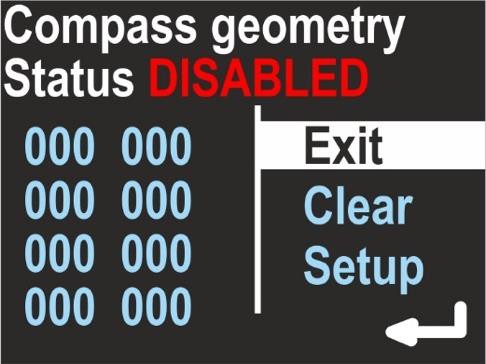
Use the top button to change the option:
Exit
Return with no changes
Clear
Switches off the precision calibration and clears all its coefficients.
Setup
Make a new precision calibration.
To make a new precision calibration, you should use the SET option. You will be asked to set the device in true geographical direction of 0, 45, 90, 135, 180, 225, 270 and 315 degrees. The device should be positioned vertically, like being attached to the DPV.
The Display shows:
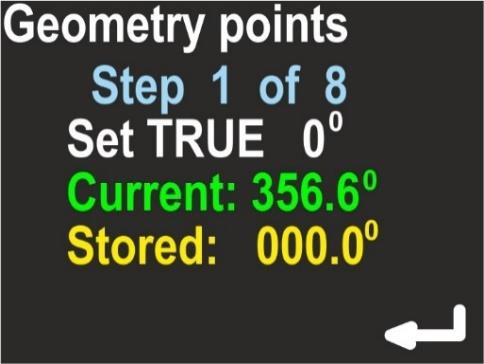
Current
Raw heading from magnetometer, without correction.
Stored
Stored value for this step.
The lower button will store the Current value as Stored, each time you press it.
The upper button will guide you to the next step.
On the last screen you can check, if this calibration improved the heading display.
This screen is named ‘Accuracy test’ and will show you:
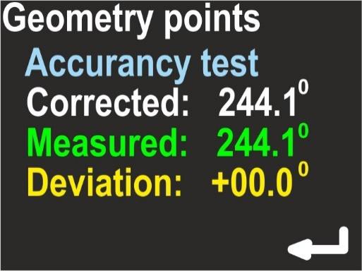
Corrected
Heading value with applied correction
Measured
Raw heading value from magnetometer
Deviation
Calculated correction; Corrected = (Measured + Deviation) mod 360.
If the corrected values are better than the measured values, press the lower button (ENTER) to store the results. If you press the upper button, no changes will be stored.
Install angle
The last new feature available in the compass calibration menu is the Install angle feature. This feature significantly increases the accuracy and repeatability of compass readings.
The electronic compass built into the ENC console will work properly only if the console is mechanically connected to the body of the underwater vehicle (scooter) in a permanent manner (unchanged throughout the entire dive). In addition, it is required that the angle formed by the screen of the device with the axis of the scooter is known and constant.
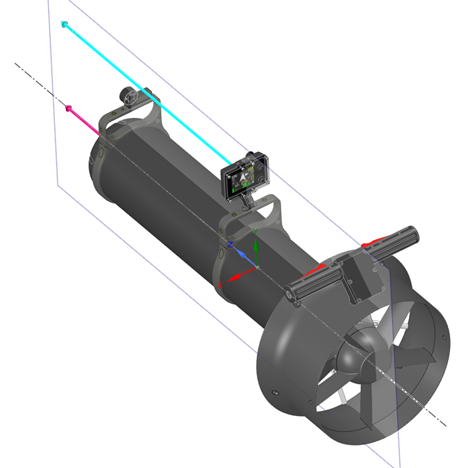
In the previous version of the ENC console software, we assumed that the user could attach the ENC console to the scooter in a certain way (fig. below), and the installation angle would be within a small range of values (0 …- 35 degrees):
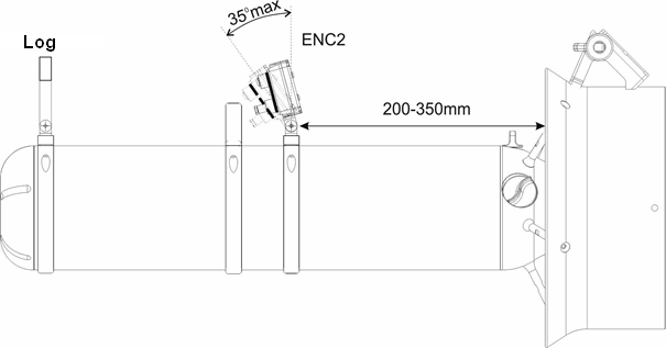
Analyzing some less typical cases, we concluded that for some divers, due to their specific habits or specific diving conditions – this simplified system is insufficient and may lead to errors in determining the direction of flow, which also tend to accumulate.
Therefore, in the current software version, the installation angle issue has its own configuration section and it is required that the user correctly configures this parameter.
What is an installation angle and why is it important?
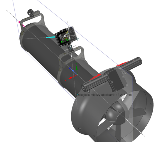
Ideally, the ENC console could be installed exactly perpendicular to the scooter hull. Such a case means that Install angle = 0 (Fig. below):
However, such a case is extremely rarely possible in practice. Due to the convenience of use, it is easier to read the ENC console’s indications when its screen is slightly tilted “forward”. This means that Install angle is negative. Additionally, the value of this angle may vary depending on user requirements. If we tilt the console a bit, then when our scooter is set differently than straight, the compass direction measured by the ENC console does not coincide with the direction of the scooter movement.
No DPV tilt- correct readings
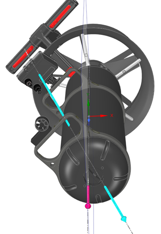
DPV is tilted- changed readings
The error will occur in case the ENC console does not compensate its indications.
In the previous version of the console software, this compensation was only possible in a narrow range of installation angle and tilt angle. The ENC console selected the correct values automatically and the user could not influence them.
Setting the installation angle
This software version allows the user to fully control all the necessary parameters.
To set this parameter, go to MENU → SETUP → Compass → Install angle.
The ENC console display will show the following:
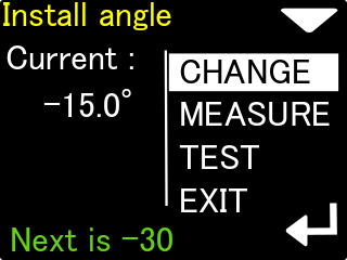
The current value of Install angle is shown.
The lower button allows you to cyclically change the installation angle:
0 …- 15 …- 30 …- 45 …- 60 … 0 … -15 …
The green text at the bottom tells you what the next value will be.
The upper button allows you to go to the next option – angle measurement (MEASURE).
Measuring the installation angle
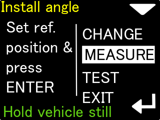
Step 1
Attach the ENC console perfectly perpendicular to the scooter hull and press the lower button once. This is how we measure the reference position (that is where the angle is 0).
The scooter should be kept as still as possible during the entire measurement.
However, it does not have to be set in any particular way.
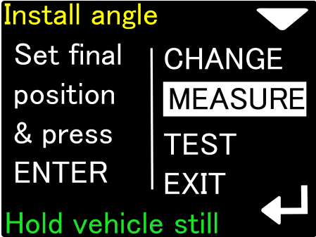
Step 2
Tilt the ENC console to the position that is most comfortable for the user.
Then press the lower key again.
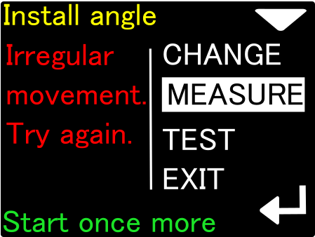
If during the Install angle measurement our scooter moves, the measurement will be rejected. The measurement can be started from the beginning with the lower button.
The installation angle measurement procedure allows you to set any angle that is convenient from the user’s point of view.
Confirming the installation angle
Select the TEST option and check, if the white dot is inside the green circle:
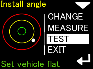
If so, our Install angle has been set correctly.
By tilting the scooter to the right or left, we will see that the white dot is moving in the opposite direction.
If the white dot is below the center, the Install angle selected by us is too small
(e.g. we set -15 and it should be -30 degrees).
The opposite is true if the white dot is above the center.
Declination
Set magnetic declination, a constant value that will be added to the heading shown on the display (and to all position calculations). If the value is marked as E (East), the correction will be positive. When marked as W (West), the correction will be negative. The magnetic declination is a constant value, depending on your geographical region. It can be obtained from many sources.
Deviation
Set magnetic deviation, a constant value that will be added to the heading shown on the display (and to all position calculations). The deviation is a constant value caused by magnetic elements near the navigation device, that cannot be removed. In most cases it will be set to 0.
Practical guide of ENC compass calibration
Described below actions are mandatory to be performed in this order, to ensure that ENC compass will operate correctly.
Based on the recent developments in the compass calibration algoritm, there are two possibilities of proceeding. The most recommended it to calibrate assembled console – mouted on the DPV or other device, in a final working position. However, if conditions does not allow for this – it is possible to calibrate it also on land.
First mandatory steps
Before starting to calibrate the compass, be sure to:
- Set the correct compass declination
- Make sure that there are no magnetic disturbancies around. (phone, metal pier, electric cables in the ground)
- Install angle is set to the correct value (especially for calibration of assembled ENC)
Calibration of stand-alone console
For diving in cold water, or difficult entry console can be calibrated by itself only. This is sufficient for most applications, and will work with Seacraft scooters- which has a low magnetic disturbance in the recommended mounting point.
In order to visualise necessary movements, you can see the video below. Current revised calibration progress bar will measure the real data collection
Calibration of assembled console
When console is assembled on the DPV/ other measurement device, calibration can be made both underwater, or on the water surface. As for example rotating the DPV in the air would require a lot of force, and DPV buyancy in the water is neutral – this simplifies to make necessary movements.
While in the shallow water, or floating on the surface, make sure that console is mounted and locked in the desired installation angle, and speed sensor/other measurement circuit is deployed in the diving position.
You can clip off the DPV attachement carabiner, to make movements easier.
Start the compass calibration. Rotate the whole DPV in the horizontal axis, changing the console position in the DPV axis while performing this rotations. (8-10 turns).
Rotate few times the DPV in it’s long axis, and looking to the ‘ground’ and ‘surface’ directions.
Finalize the calibration by making smooth and random rotations, attempting to recreate all possible positions.
You should read 120% of progress bar and accept the calibration.
Take care that calibration Match factor is at least above 86%.
You can watch this instructional video:
: https://www.youtube.com/watch?v=BjgbjSIU5Ow
Calibration validation in the water
There is a simple way of checking the compass calibration quality, and device functioning. It can be made before more serious dive, or as a training task.
Choose a fixed reference point at the shallow water – it should be big, and clear. Diving platform, marker on a line, or characteristic rock are ideal.
Start a new track on the ENC (turn it OFF and ON underwater)
Start driving in choosen direction (for example following a coastline). Drive for 150-200m, it does not need to be a straight line. At this point, press the RETURN button and start the way back.
Drive back to the reference landmark. Excactly at the point where you started to drive before, read ‘how many meters to the target’ are left. This is a absolute measurement error. For example, we have here 12m.
Read also the total track distance. For example, we read 436m here.
Our loop closure error is here: 12/436 = 2,75%.
The lower % error, the more precise navigation was. It should be not especially challanging to get below 5% of total error. 2% is considered a good result (while driving the DPV). Experts are able to get around 1% of error.