Introduction
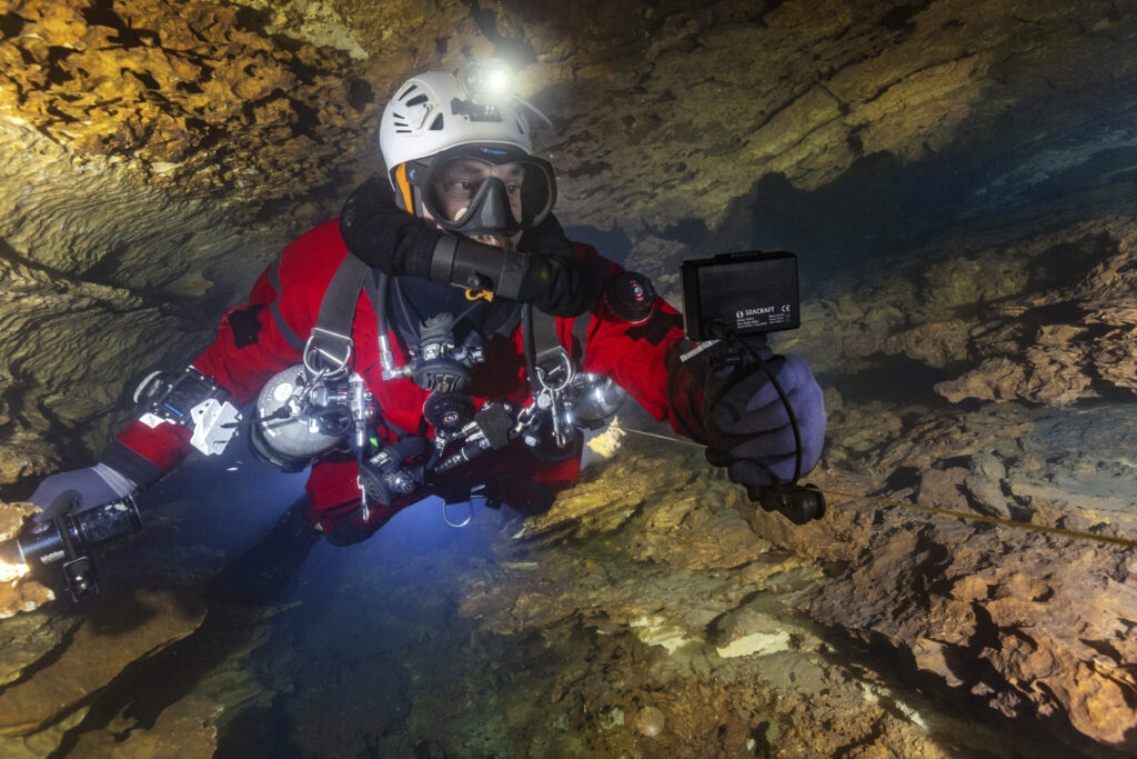
The Surveyor is an accessory for ENC3 navigation console. It allows for measurement of tensioned lines, which are often used as reference – for example, for cave diving survey, or archeological survey.
While the DPV-mounted ENC3 survey is a very fast and precise measurement method, it will be difficult to use in tight environments (restricted caves), or with strong variable current present. For the the highest accuracy level a permanent reference grid measurement is always the best option.
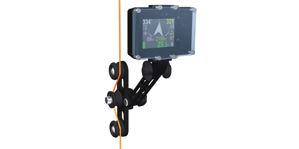
Mechanical construction
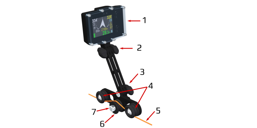
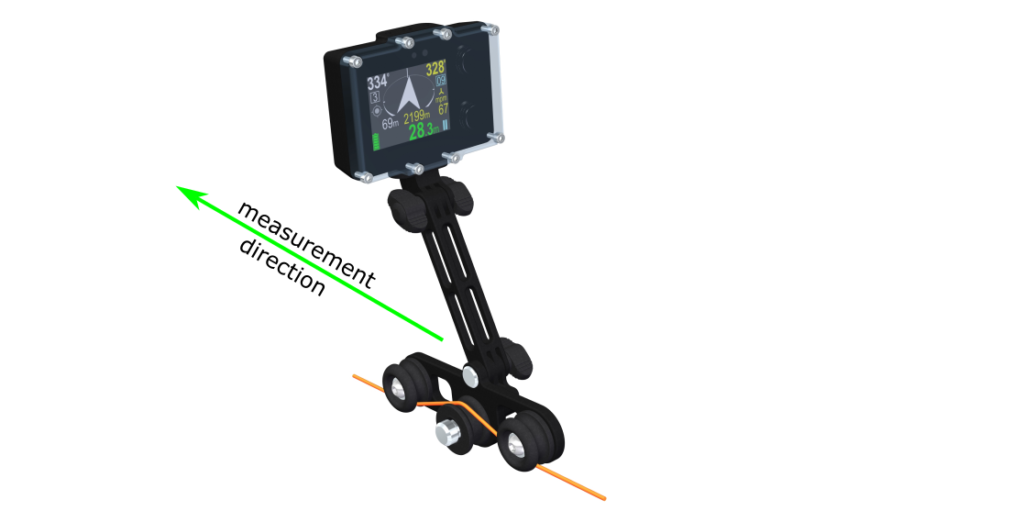
- ENC console compatible with The Surveyor connector standard. (ENC3 connector)
- Top connection. Used is a double-nut screw, which requires that ENC3 console is equipped with a 3-arm attachement bracket without thread.
- Bottom connection. Between 2 and 3, there is a structural extension – arm – located. It moves the console magnetometer away from measurement wheel, which contain magnets.
- Guide wheels. This set of wheels is used to position The Surveyor on the guideline only
- Guideline/ tensioned line. This line is measured now by the Surveyor.
- Measurement wheel. This wheel contains magnets, which allow to count the number of it’s rotations.
- Measurement wheel screw. In case of fine sediments blocking the measurement wheel work, this screw can be used underwater for cleaning the gap between the wheel, and device.
- Wheels 4 and 7 are mounted to the Surveyor body, which contains a measurement circuit, and cable connector.
Preparation for diving
Assembling the Surveyor
Make sure that the ENC console is fully charged. Connect the console to the Surveyor’s arm, and connect the cable connector. Ensure that o-rings are well lubricated, and without impurities or damage.
For transporting the Surveyor to the beginning of survey work, it can be folded and made more compact – for example, to fit it into pocket/pouch, or clip to the transport D-ring.
Take care to not create a tight bending on the connecting cable, and avoid exposing the cable connector for contact with sharp objects when diving.
It is recommended to add a small loop made from a line, to create a possible attachment place for a double-ender carabiner, or another method which allow clipping of the device to the diver, depending on the environment it will be used in.
Configuring the ENC
Several configuration settings should be correctly set-up in the ENC settings menu in order to be able to work well with the device.
Due to the survey work nature, we recommend having following settings prepared as described below. There are other configuration possibilities that may fit better a particular task, and for advanced users understanding ENC work principles they can be freely changed.
The list of recommended settings. If a parameter is not listed here, this means that it’s importance for correct operation is not too big.
- Record every – 5s. The nature of hand-survey work is slower than when DPV is used, and usually does not need to have a 2s mandatory data saving interval. The more frequent forced data save is, the more ‘excesive’ points may be added
- Depth threshold – 0.5m. As many surveys may begin/end on the water surface, or run very shallow – this setting prevents some other settings to react in undesired situation.
- Auto-ON – No. As often arriving to the moment of survey beginning will take time, there is no point to drain ENC battery before this happens
- Auto-OFF – Yes. Forgetting to turn OFF the ENC, or accidental activation in transport may render the device unusable (discharged) when it is needed.
- Auto-REC – No. Fine positioning of Surveyor may require to move the device on the line prior to starting registering.
- Auto-HOLD – No
- ENC should be operating in a mode of diving without a destination. In the future, it is possible that a dedicated survey mode will be introduced.
Calibration of speed setting
ENC will register the device’s progression based on counted impulses number. Their connection with diver driving a DPV is slightly variable. This is described in the chapter about ENC speed log calibration.
As the Surveyor uses a different metering circuit, its calibration coefficient needs to be changed when switching between DPV measurement, and Surveyor measurement.
Set the speed log for ‘External log’, and set calibration factor: 2762
This value indicates that for a 100m distance, 2762 impulses are created – one per each 3,62cm. This means that the minimum Surveyor resolution is 3,62cm. (after moving this distance, an impulse is sent).
This calibration factor will be not depending on the line thickness. In general, the Surveyor can be used with 1-3mm lines, which can be knotted. Thicker lines can be also measured, however knots may cause difficulcities.
Calibration of compass
In order to operate properly, ENC compass has to work with the highest possible precision. Read the compass calibration page in the ENC manual.
It is recommended to set ‘Install angle’ to 0*, and attempt to keep the device as vertical during measurement as possible. (it will be explained later)
The ENC compass should be calibrated while attached to the Surveyor, in ready-to-measure position. It can be done prior to diving, or underwater.
Make sure to do it in a magnetic-disturbance-free environment, without any watch, phone in the pocket, or other electronic devices in the nearest vicinity.
In general, the Match factor (which indicates the calibration quality to some level) should be around 90%, the best – above 90%. Any value below 80% indicates that calibration is not sufficient to perform a precise survey.
Setting a correct declination, and salinity
Remember to set a correct declination, for an area where the survey will be performed.
Check if the set water salinity is correct for the planned diving environment.
Underwater measurement
General idea
The Surveyor will measure and save the line polygon between line fixing points. Distance measurement is made based on direct contact of measurement wheel with the line surface, which causes it to spin and send progression information to the ENC.
ENC is measuring depth, and compass direction, which combined together are saved as the line measurement file.
Due to constant measurement, placements, or angled line positioning is not a problem. However- as each line contains some stabilisation points (tie-off’s), and can have a line marker tied, there are some special situations that need to be remembered about.
Line tension
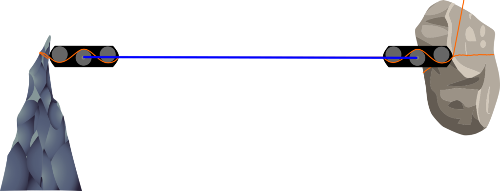
The Surveyor can be placed on the line in 2 modes of line threading:
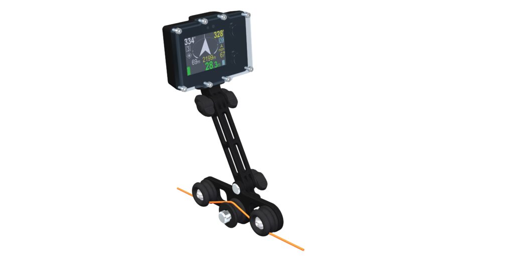
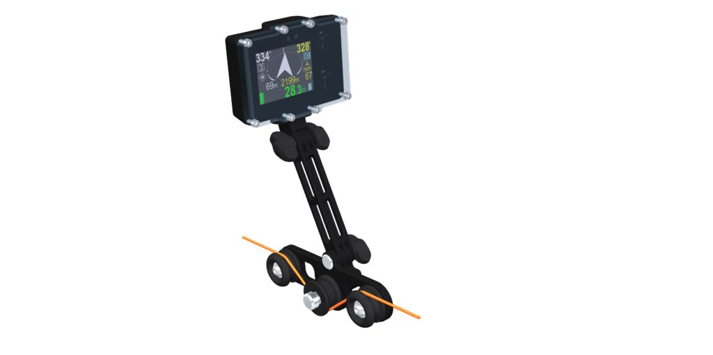
If the line is well-tensioned, use position A.
For a looser line, use position B.
For completely slack lines, there is even the possibility of wrapping the line around one of the wheels.
The key is to:
- Not create too big tension, as this makes moving the Surveyor difficult
- Ensure that line is wrapped tight enough to keep the measurement wheel spinning reliably
Taking a measurement
Single distance
After completing all of the pre-dive preparations, we are ready to start measuring underwater.
Let’s begin with the first tie-off. It is recommended to start from a well-defined point, that can be later tied in the other survey (marked survey station), or georeferenced.
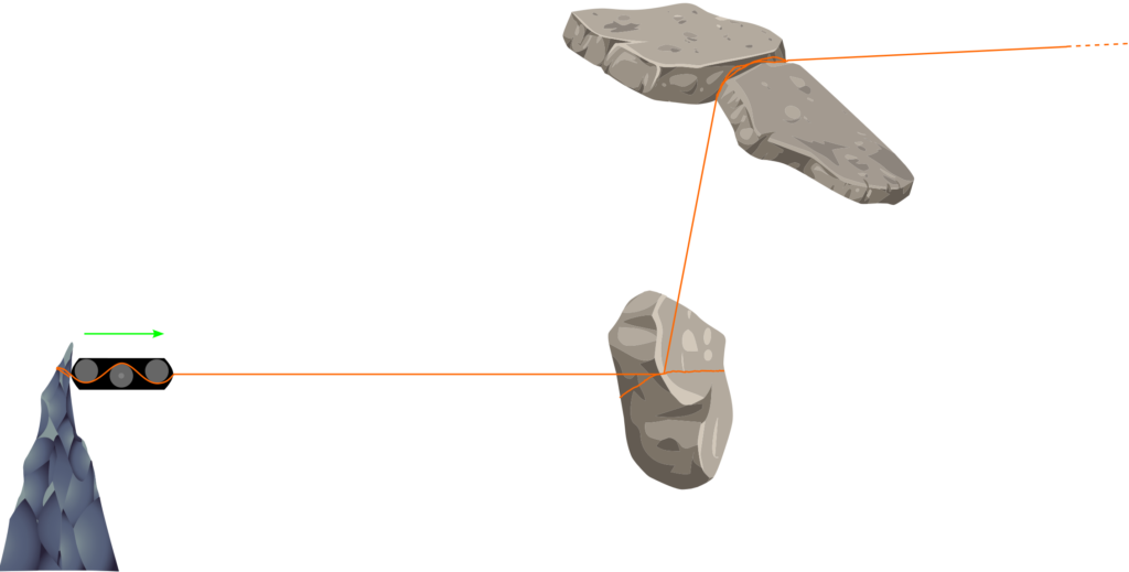
The Surveyor position is marked as a 3-wheel icon representation to simplify the drawing. Drawings have no scale- in reality, the device is much smaller.
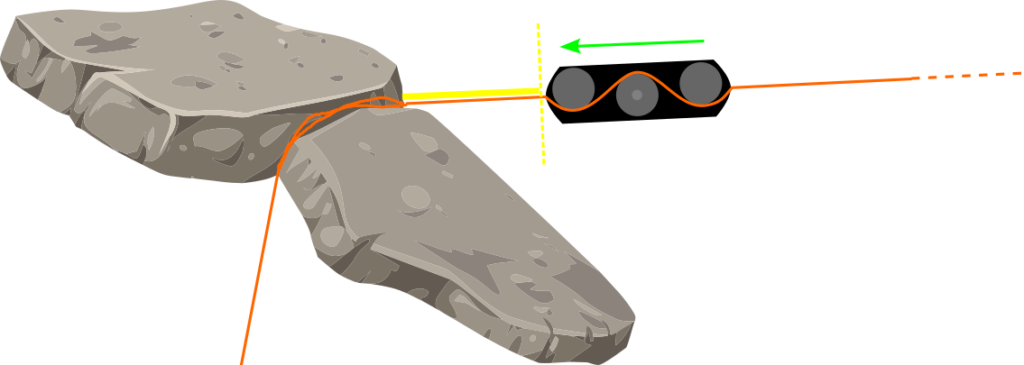
Place the Surveyor as close to the tie-off as possible. It should be orientated in a way that ENC screen faces toward the diver who dives in the direction of measurement. (even if he is actually squeezing backward through a narrow fissure)
Press the REC button, and make sure that ‘REC(ording)’ indicator – a red blinking icon – is visible.
Now, gently push the Surveyor, keeping the ENC console as vertical as possible. The console should keep a 0* angle in regards to the Earth’s ground level. (if such Install angle is set). This means that for a guideline parallel to the ground level, the console should be placed completely vertical (as on the drawing above)
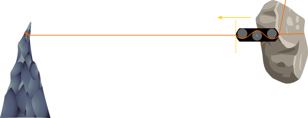
At some point, the next tie-off will be reached, as indicated below.
A careful observer would realize, that distance traveled by the measurement wheel is not equal to the line length between tie-off’s. This is due to the length of the Surveyor.
At the start and end, half of its length separates the measurement wheel from reaching the absolute end of the line.
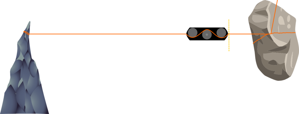
In order to measure the real line length, a simple precision-increasing trick can be used. As the measurement wheel does not recognize the direction of rotation (and assumes that all progression is made forward)
Move the device a whole of its length backward:
Now, the device can be stopped (REC to HOLD), and taken off from the line.
There is an additional good point about this approach.
When REC status is changed to HOLD, a WPT – Waypoint is logged.
This means, that by every REC/HOLD transition, a new waypoint is saved, and its number is displayed on the ENC screen. These numbers can be described separately as for example possible side-branch, T intersection, or an archeological artifact location- depending on the realized task.
Passing an obstacle
There is a possibility, that we will encounter an obstacle mid-way, which will require us to take the Surveyor off from the line. If this is a small object (a large knot, line marker, connected jump), you should proceed in the same way as when encountering a tie-off.
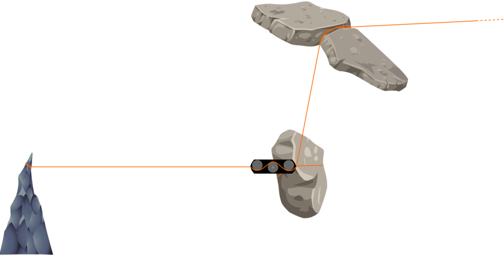
Let’s start measuring the next leg. Place the device at the tie-off, activate REC, and move the Surveyor towards the next tie-off.
Unfortunately this time, the line stabilization is not made very well. It is not possible to move the device up to the end of the line, as it is just wrapped around the big boulder. Let’s get to the end, move a Surveyor length backward switch REC to HOLD, and consider an action that allows compensating for this.
We have some distance that cannot be measured (represented by a yellow line)
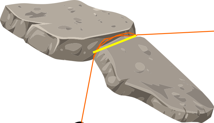
In order to manage this, we should choose if ‘adding the length’ will be made at the end, or beginning of the tie-of. It could be also split into both of them, however, practically wise, just one side, better corresponds with the ‘lost measurement’ directions chosen.
Here, the angle is more similar after this tie-off, thus we will add the length there.
Move the Surveyor a distance equal to the yellow line from the tie-off, and press REC.
Now, move the Surveyor to the tie-off/obstacle, and later start moving it towards the next direction. (this is made without removing the device from the line)
Do not forget to add a device length at the end of the measurement.
This method does not provide a 100% precision, but with relatively small distances (20…40cm) it allows to significantly reduce error from obstacles located on the line.
Proceed in this manner, until the survey is finished.
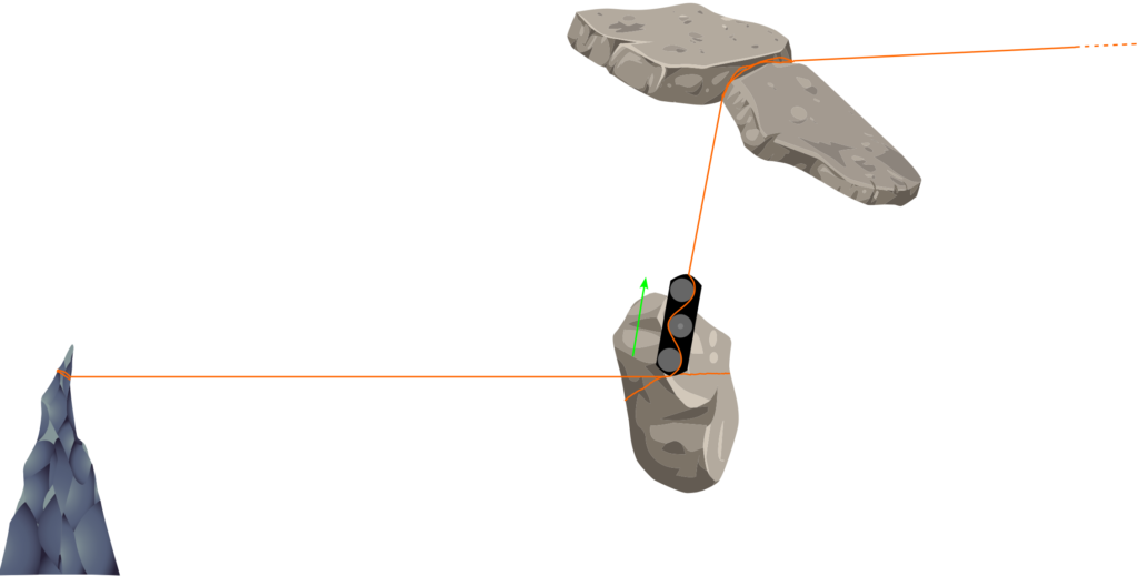
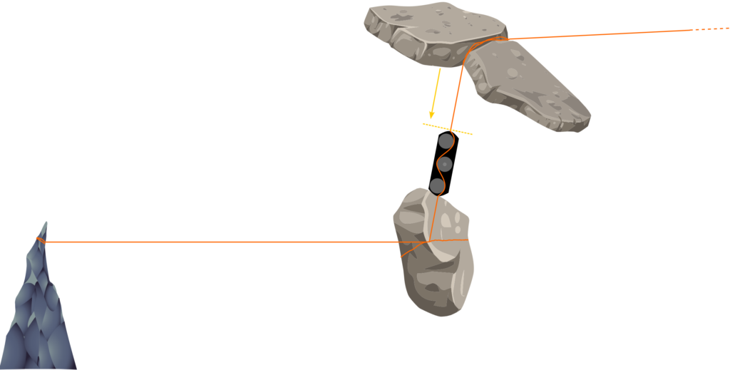
Inclined lines and shafts measurement
In case that a vertical, or highly inclined line, use the Surveyor as described before. Make sure that the console is correctly inclined – the picture below indicates its orientation in a vertical shaft.
Starting a new track underwater
If there is a necessity to start a new track underwater, be aware that if the measured track has below 10m in length, it will be not saved.
Go to the menu, and TURN OFF the device. After powering it ON, a new track will be started, with a new, higher track number.
The track can be viewed underwater using a GRAPH, and Swim route Graph visualization. (both – plan and profile)
Data processing
Registered track workflow
In order to get the data from the ENC, read the supplementary software information in the ENC manual.
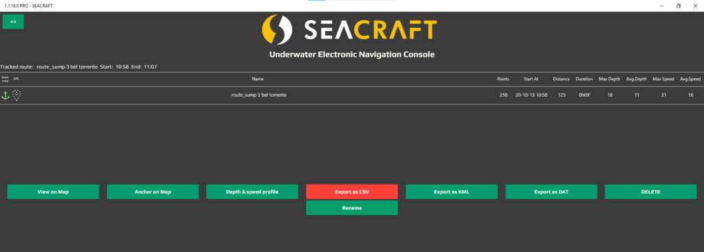
Having track downloaded into the Seacraft program for Windows 10, we need to start by anchoring it. This is mandatory for the program to allow for the next steps. As we often do not know the exact starting point- a track can be anchored anywhere, for example in the middle of the Baltic sea.
If we made any mistakes before as forgetting to add the declination, or wrong calibration factor- when anchoring the track, this can be corrected. (and will modify .csv file content)
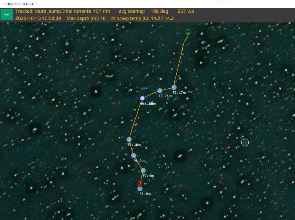
In this example, we have a short sump (107m) survey. Tie-offs can be clearly seen as waypoints.
Next, we would like to export the .csv file
CSV. means comma-separated-values. It is an open, and simple format which can be read by any device or computer without problems.
For this example, we will use an Excel spreadsheet to access and organize the data.
Open a new file, and click: DATA–> Import from text
Use ‘comma’ as a data separator, and format all colums as ‘text input’.
This should result in a similar table as below, with all data logged by ENC at the converted track.
ENC data format
ENC is saving a track using its own file representation format.
In order to use efficiently ENC for survey work, it is mandatory to understand well it’s structure.
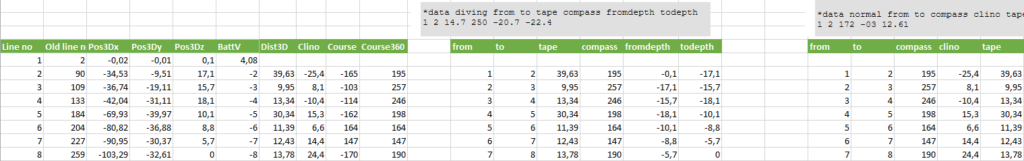
After importing a csv. file into Excel, we should see data as follows:
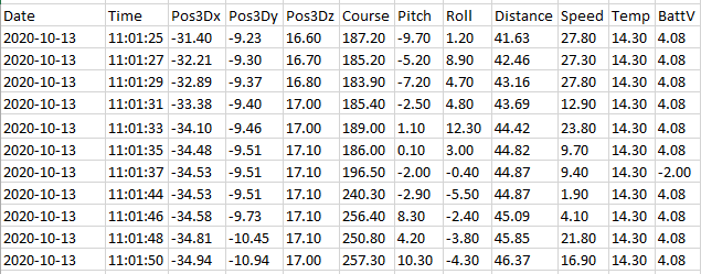
What is most important, is the fact that course/distance/speed, are only momentary data, and should not be used for track conversion.
Only X,Y,Z positions should be used. These are relative distances from the 0,0 point (start point), of each particular point saved by the ENC.
Waypoint presence is saved under the ‘BattV (battery voltage)’ parameter, with a ‘-‘ sign. Visible here ‘-2’ indicates waypoint 2.
For some cave survey programs, this data notation is already good enough to directly paste inside.
Point reduction
In this 130m survey, there are 263 points. Importing all of them into survey software can be very loading for it, as usually the amount of points is much lower.
Also, usual dive survey notations are different – with the most common (and accepted by virtually all known programs) being:
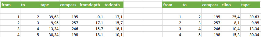
- From – starting survey station name
- To – ending survey station name
- Tape – straight length between the points
- Compass – bearing From To
- Clino – clinometer (angle of line between point From and point To)
- fromdepth – From point depth
- todepth – To point depth
In order to facilitate track conversion, we prepared a small Excel sheet which makes this work easy.
It allows performing point reduction (to decrease data intensity) and direct conversation to the diving formats.
For example. Using the sample file, we paste it into the converter:
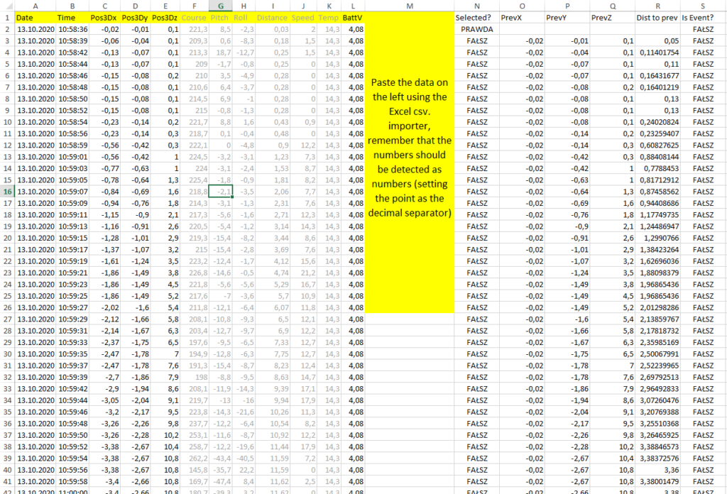
We set the reduction parameters to ‘999’ and ‘FALSE’
As the output- our 263 points are reduced to just an 8-station survey, the same as it would look like in a normal cave survey.
The same converter can be also used for data obtained by diving with a scooter and ENC.
Survey data in this format can be easily pasted and processed to any type of used cave survey software.
Data precision
There are certan precision limits, which are corresponding to the overall end-effect.
- Temperature reading may require up to 20-30s to adjust, for example after crossing a thermocline
- Compass precision with correct calibration – below 2.5* (see FAQ for compass precision definition)
- Depth sensor maximum error – 0,3m. Due to reliable reading range up to 300m, there may be situations where depth is recorder with +-0,3m precision
- Length measurement resolution – 3,62cm. The length measurement error, under optimal conditions cannot exceed this value.
- Compass precision in the hand-survey mode – below 2,5* with correct calibration. See ENC manual for details.
- Loop closure error. With proper calibration and usage of the device, loop closure error of the measurement is around 1%.
Troubleshooting
| Symptom | Cause | Solution |
| The measured length is not correct | Wrong calibration factor | Check if calibration factor was changed to the Surveyor appropriate value |
| Impurities in the measurement wheel | Unscrew the measurement wheel screw, and clean the measurement wheel. | |
| Big loop closure error | Improper compass calibration | Calibrate the compass |
| Not keeping the Install Angle | Check what Install Angle is set, and keep it during the measurement | |
| Impurities in the measurement wheel, stopping it occasionally | Unscrew the measurement wheel screw, and clean the measurement wheel. | |
| Distance is not measured at all | Damaged cable or cable connector | Clean the connector, if this does not help – contact Seacraft service |
| Damaged magnets | Disassemble the measurement wheel and inspect the magnets for damage/corrosion | |
| Blocked measurement wheel | ||
| Wheel is not operating smoothly | Too tightly tensioned wheel | Release 1/8 of turn of blocking screw, and check again |
| Dirt/ material damage | Disassemble the wheel, clean tit and it’s contact area, and inspect for material scratches |